
High-strength structural bolts are small components with system-level consequences. Their performance depends on the complete assembly, the connected plies, the faying surfaces, installation method, calibration and inspection—not simply whether the nut appears tight.
Because structural bolting standards differ by jurisdiction and project, this article presents a quality-control workflow rather than universal torque values. The engineer’s design documents, applicable standard, bolt manufacturer’s instructions and approved method statement remain controlling.
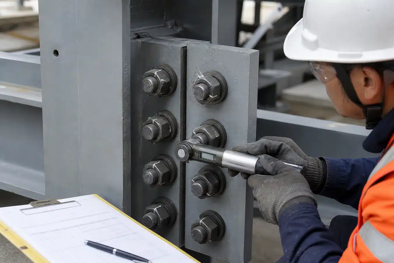
Clarify the connection and acceptance basis
Before material arrives, the team should identify whether the joint is specified as snug-tightened, pretensioned or slip-critical, and which bolting system and standard apply. That decision affects surface preparation, installation and inspection.
The inspection plan should define lots, required documents, sampling, storage, pre-installation verification, installation method, responsibilities and records. Mixing requirements from unrelated standards can produce unsafe or uninspectable work.
Receiving: verify complete assemblies by lot
Bolts, nuts and washers should be received as the specified matched assemblies, with grade, dimensions, finish, manufacturer and lot identity checked against the purchase order and certificates. Packaging should preserve traceability. Damaged, corroded or contaminated components should be segregated pending disposition.
| Receiving check | Purpose | Record |
|---|---|---|
| Markings and dimensions | Confirm specified type and grade | Receiving inspection |
| Certificates and lot identity | Maintain traceability | Certificate register |
| Assembly condition | Detect damage or altered lubrication | Condition report |
| Required verification tests | Confirm lot performance under the applicable code | Laboratory or site test report |
Testing requirements depend on the bolting system. For example, some specifications assess torque coefficient while others use tension or pre-installation verification. Procurement documents should state the required tests rather than assume every “high-strength bolt” is interchangeable.
Storage protects installation behaviour
Assemblies should remain dry, covered and organised by lot. Threads and manufacturer-applied lubrication must be protected from dirt, moisture and unapproved treatment. Field relubrication, cleaning or substitution should occur only through an authorised procedure because these actions can change the relationship between applied torque and bolt tension.
Prepare holes, plies and faying surfaces
Connected plies must fit together as detailed. Burrs, distortion, excessive gaps and misaligned holes can interfere with seating. Unauthorised flame enlargement or forced assembly is not an acceptable correction. Any hole modification must follow the engineer-approved procedure and governing standard.
For slip-critical connections, the prepared faying surfaces must provide the specified slip resistance. Oil, uncontrolled paint, overspray, heavy rust, dirt and moisture can compromise performance. Surface condition should be protected through transport and erection, then checked before the joint is closed.
Install the correct component orientation
Bolt direction is normally selected for access, inspection and consistency unless drawings require otherwise. Washers must be placed as required for the assembly and installation method. Threads should project sufficiently for full nut engagement, while grip length and thread location should remain within the approved configuration.
Bolts should not be used to draw severely misaligned steel into position. Temporary pins and erection bolts may assist fit-up under an approved method, but the final plies should be in proper contact before pretensioning begins.
Use a verified tightening method
Common pretensioning methods include calibrated wrench, turn-of-nut, tension-control bolt and direct-tension-indicator methods. Each has distinct verification and inspection requirements. A method is not interchangeable merely because the crew owns the tool.
Pre-installation verification should use representative assemblies and the actual installation tools as required by the applicable standard. It confirms that the selected procedure can achieve the required condition and helps identify issues such as unsuitable lubrication or tool settings.
- Bring the joint to the required initial condition across the connection.
- Follow the approved tightening pattern, typically progressing systematically from the stiffer part of the joint toward free edges.
- Complete pretensioning within the permitted sequence and time window.
- Do not reuse assemblies unless explicitly permitted by the applicable specification.
- Apply completion marks where the inspection plan requires them.
Inspect the method—not only the finished appearance
Inspection should observe the work at defined stages. For turn-of-nut installation, the initial condition, match marks and prescribed rotation are relevant. For tension-control assemblies, spline removal may form part of acceptance but does not replace all checks required by the governing procedure. Calibrated-wrench methods depend on tool calibration and controlled installation conditions.
Post-installation torque checks are not a universal proof of achieved pretension because friction, relaxation and test timing affect the reading. Use only the inspection method recognised by the project standard. Nonconforming assemblies should be evaluated, replaced or reinstalled through a documented disposition.
Respond consistently to nonconforming installation
When a bolt cannot be installed or accepted as planned, the response should not be improvised. Examples include damaged threads, missing washers, a failed verification test, contaminated faying surfaces, an incomplete spline break or suspect tightening marks. The affected assembly or work area should be identified and held while authorised personnel determine the disposition.
Replacement is often clearer than attempting to recover an altered assembly, but the governing specification and engineer must control that decision. If removal may disturb neighbouring bolts, the repair sequence should consider the condition of the complete joint. Reinspection should then demonstrate that the approved correction was implemented.
Coordinate bolting with coating and fire protection
Bolted connections frequently sit at the boundary between structural installation and finishing trades. Overspray on slip-critical surfaces, sealant placed before inspection, or fireproofing applied before joint acceptance can conceal problems. The programme should keep connection faces protected, define permitted coatings, and delay covering work until bolting records are complete.
After acceptance, exposed edges and connection zones may need corrosion-protection touch-up according to the coating specification. This final treatment must not be confused with painting faying surfaces before assembly; they are separate technical decisions.
Close the traceability loop
Records should link the connection or work area to bolt lot, installer, date, method, tools, pre-installation verification, inspection result and nonconformance status. Clear shift handovers and completion marking reduce the risk of missed bolts in dense connections.
A strong bolting process is deliberately repetitive: receive, protect, verify, fit, tighten, inspect and record. For questions about steel fabrication documentation and connection-quality interfaces on a potential package, please Contact Us.