
For many structural steel projects, BIM still arrives too late. The engineering team completes drawings first, and a separate team then rebuilds those drawings as a three-dimensional model for coordination or client presentation. The result may look convincing, but it is not necessarily reliable enough to drive fabrication.
Forward BIM for structural steel takes a different approach. The coordinated model is developed as a controlled source of design information, while drawings, schedules and downstream fabrication outputs are generated from that source. This does not eliminate engineering review, shop detailing or production checks. It does, however, reduce duplicated data entry and make changes easier to trace.
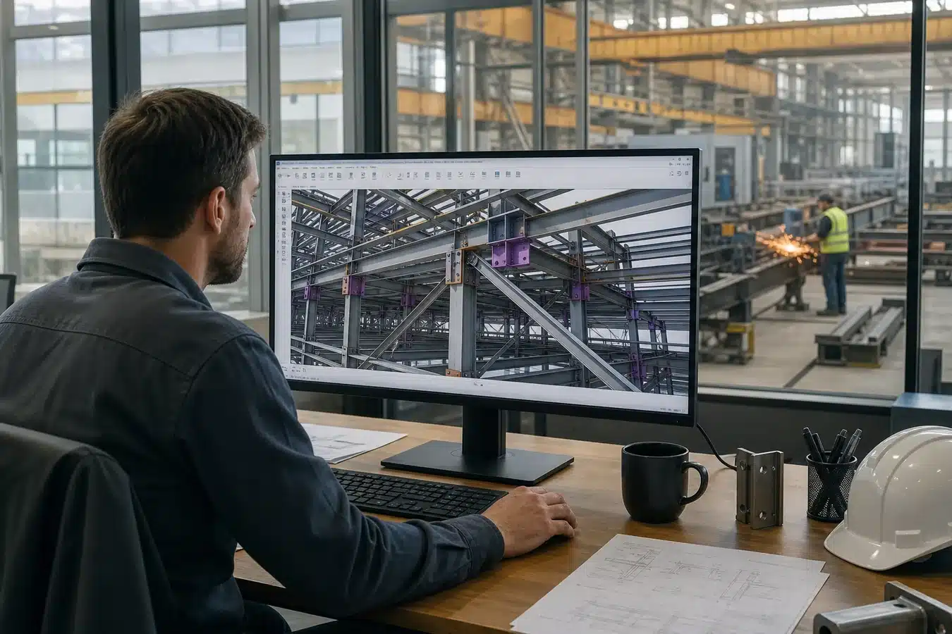
Retrospective modelling versus a data-led workflow
A model recreated from completed drawings is useful for visualisation and selected clash checks. Its limitation is that member marks, connection objects, material grades and revision status may have been added after the engineering decisions were made. If a drawing changes, the model can become another document requiring manual reconciliation.
In a forward workflow, geometry and object information evolve together. Each member has a stable identity, defined properties and a known relationship to grids, levels and adjacent systems. The model can then progress from structural intent into connection detailing, shop information and machine-readable production data—subject to approval gates.
| Issue | Retrospective model | Forward BIM workflow |
|---|---|---|
| Primary purpose | Visualisation or contractual model submission | Coordinated source for design information and downstream outputs |
| Change control | Drawings and model may require separate updates | Approved outputs are regenerated from a revised source |
| Fabrication value | Often limited by incomplete attributes | Potentially supports detailing, quantities and CNC preparation |
| Main risk | Inconsistent documents | Poor standards or uncontrolled interfaces corrupt downstream data |
Why structural steel depends on accurate model data
Structural steel is manufactured before it reaches the site. A wrong hole pattern, plate orientation or member length cannot always be absorbed by field adjustment. Complex connections, non-repetitive members and numerous interfaces with concrete, façades and building services make completeness especially important.
A useful steel model should make connection zones understandable, but visual clarity alone is not enough. It also needs consistent coordinates, section and material definitions, member orientation, assembly logic and unique marks. These attributes support checking and traceability; they should never be treated as decoration added immediately before issue.
Five links in the design-to-fabrication chain
1. Define model uses and responsibilities
Before modelling begins, the owner, engineer, detailer and fabricator should agree what the model will be used for, who owns each information field, which outputs are contractual and which software versions or exchange formats apply. A model intended only for coordination requires different content from one intended to support fabrication.
2. Preserve design intent during detailing
Structural analysis models and steel detailing platforms rarely contain identical information. Transfers may lose releases, offsets, connection assumptions or object classifications. The receiving team therefore needs a documented validation process rather than assuming that import success means engineering equivalence. Connection design and shop-detail approval remain controlled engineering activities.
3. Prepare fabrication data safely
A detailed model may generate bills of materials, plate nests and numerical-control files. Typical workflows export NC data to cutting or drilling software, but automated output is only as dependable as the source model. Before release, teams should validate numbering, material grades, units, hole geometry, coordinate conventions, revision status and machine compatibility. Direct export does not remove independent production checks.
4. Coordinate physical interfaces early
Federated coordination can identify beams conflicting with ducts, anchor rods intersecting reinforcement, façade brackets lacking clearance or penetrations cutting through critical steel zones. The priority should be actionable clashes, not a large unfiltered report. Every issue needs an owner, due date and recorded resolution.
5. Simulate assembly and erection
Digital trial assembly can test whether adjoining pieces, bolts and access zones are compatible before physical work begins. For large roofs or complex trusses, sequence simulation can also review temporary stability, crane access and laydown constraints. These exercises support planning but do not replace engineered lifting studies, temporary-works design or site risk assessment.
Information required at handover
Owners sometimes ask for an asset model at project completion without defining the data needed to operate the facility. This usually creates an expensive late-stage clean-up exercise. If the model is expected to support maintenance, the employer’s information requirements should identify maintainable assets, naming conventions, document links, classification and acceptance tests from the outset.
- Set a project coordinate system and model breakdown strategy.
- Use unique, persistent member and assembly identifiers.
- Publish naming, revision and approval rules.
- Test data exchange on a representative sample before full production.
- Separate approved fabrication information from work in progress.
- Record model checks and exceptions at every release.
Governance matters as much as software
A common failure is to buy modelling software without changing approval and release practices. Teams need a common data environment, named information owners and status codes that distinguish shared coordination data from approved construction or fabrication information. Model federation should occur on an agreed schedule, with issue logs linked to revisions. These controls help prevent an apparently current model from being paired with superseded drawings or machine files.
Performance should also be measured carefully. Useful indicators include coordination issues closed before fabrication, rejected data exchanges, drawing-model discrepancies and production releases returned for correction. Claims about saved time or material should be based on project records and an agreed baseline, not assumed simply because BIM was used.
Practical procurement questions
Owners and EPC teams should ask prospective suppliers to demonstrate a controlled workflow, not simply show attractive screenshots. Request a model execution plan, responsibility matrix, sample exchange, checking procedure and clear list of deliverables. Ask how revisions propagate to drawings and NC files, how superseded data is blocked, and how the shop verifies machine output.
A sensible implementation often starts with three foundations: standard modelling rules, unique component identification and validated fabrication exports. Broader uses can be added once those foundations perform reliably. If you are preparing a structural steel package and want to discuss model deliverables, fabrication interfaces or document expectations, please اتصل بنا.