
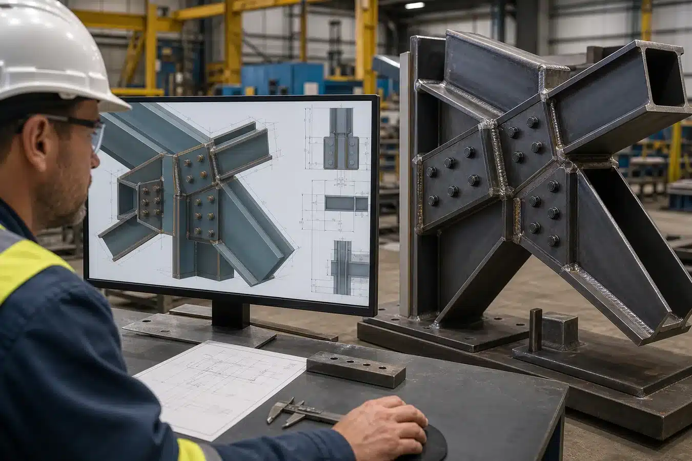
Connections are where analytical design becomes physical construction. Forces shown in a model must pass through plates, welds, bolts, stiffeners and bearing surfaces that can actually be fabricated and assembled. For owners, EPC contractors, engineers and steel buyers, structural steel connection detailing is therefore not a drafting exercise. It is a controlled translation of design intent into fabrication and erection information.
Responsibilities vary by contract. In some projects, the engineer of record provides fully designed connections; in others, a delegated connection designer completes defined work under specified criteria. Detailers must not make unapproved engineering changes. A sound workflow clearly separates design responsibility, detailing responsibility, checking and approval.
Establish inputs and design responsibility
Detailing should not begin from an incomplete drawing set without a managed assumptions register. Required inputs may include design drawings, connection schedules, loads or reactions, governing standards, material grades, fire or corrosion requirements, architectural interfaces, equipment data and erection constraints.
The project should define who resolves discrepancies and how revisions are communicated. Connection details can affect member length, plate procurement, CNC data and shipping sequence, so late changes propagate quickly. A register of technical queries and drawing revisions helps ensure that the shop does not manufacture from superseded information.
Review constructability, not just geometry
A three-dimensional model can appear clash-free while remaining difficult to build. Constructability review asks practical questions: Can a welder reach the joint and maintain the required angle? Is there access for cleaning and inspection? Can the selected wrench or tensioning equipment engage every bolt? Is there room to insert the bolt? Can the completed assembly be coated, lifted and transported?
Common risks include stiffeners obstructing weld runs, bolts too close to adjacent plates for installation tools, backing or run-off tabs that cannot be removed as specified, and connection plates that conflict with services. Review should also consider erection access and temporary conditions. A connection that works only after surrounding members are installed may be impossible in the planned sequence.
Coordinate welds, bolts and inspection access
Weld symbols and connection notes must identify the intended joint without ambiguity. The detail should communicate weld type, size, extent, contour and any special preparation as required by the governing standard. Designers and detailers should avoid prescribing inaccessible welds or sequences that create excessive restraint.
Bolted connections require equal care. Hole type, diameter, spacing, edge distance, faying-surface condition and installation method should be defined where relevant. The team must use the applicable project standard rather than transferring tolerance values from an unrelated code. Inspection access should be considered at the same time: a weld selected for volumetric examination needs suitable geometry and scanning access.
Plan for tolerance accumulation
Individual parts can meet their tolerances while an assembly misses its interface because variation accumulates in one direction. Critical dimensions should be identified from the erection interface backward. These can include column base geometry, bearing locations, splice hole groups, truss panel points and interfaces with embedded items.
Dimensioning should support how the component will be made and checked. Functional datums are more useful than chains of dimensions that accumulate error. CNC files require controlled issue and verification against approved drawings; automation reproduces incorrect data very efficiently if the release process is weak.
Convert approved details into a fabrication plan
Before cutting, production engineering should review material availability, cutting sequence, edge preparation, assembly fixtures, welding sequence, machining and inspection points. Weld shrinkage and distortion are particularly important around thick, restrained nodes. Balanced welding, suitable sequencing, fixtures and planned allowances may be used, but any method must remain consistent with approved procedures and engineering requirements.
| Detailing question | Fabrication consequence | الرقابة |
|---|---|---|
| Can the joint be accessed? | Incomplete weld or unsafe work position | Access envelope review |
| Can every bolt be installed? | Site modification or unclosed connection | Tool and insertion clearance check |
| Where is the functional datum? | Tolerance accumulation at interface | Datum-based dimensions and inspection |
| Will welding move the hole group? | Mismatch during assembly | Sequence review and post-weld verification |
| Can the weld be examined? | Specified NDT cannot be performed | Inspection-access review before approval |
Control holes and connection faces
Hole accuracy is best managed as part of a stable process, not by corrective enlargement at site. The fabrication method should consider whether holes are produced before or after welding, how parts are located and how distortion could change the pattern. The applicable drawings and standard determine permissible correction; unauthorized flame cutting or enlargement should not be treated as a routine solution.
Connection faces may also have special requirements. Bearing surfaces, slip-critical faying surfaces, machined ends and areas excluded from coating should be clearly identified and protected through fabrication and transport. Member marks need to remain visible without compromising those surfaces.
Use trial assembly selectively
Trial assembly is valuable when geometry is complex, several components converge at one node, field adjustment is limited or the specification requires verification. It can demonstrate fit, orientation and access before dispatch. However, trial assembly is not a substitute for process control, and assembling every routine connection may add cost without proportional value.
The trial plan should define what is being proven, which measurements will be recorded, the acceptance criteria and how matched components will be marked. When physical assembly is impractical, controlled templates, survey data or digital dimensional verification may address specific risks.
Issue a fabrication-ready connection package
- Approved shop and assembly drawings with clear revision status
- Connection design approvals within the contractual responsibility
- Material and fastener specifications
- Welding and inspection requirements
- Critical dimensions, datums and tolerances
- Member marks, orientation and erection references
- Defined hold points and trial-assembly requirements
The best details reduce the need for workshop interpretation and site improvisation. They do not merely fit on screen; they can be fabricated, examined, handled and erected using the planned methods. Early collaboration among engineering, detailing, production, inspection and erection planning is the most effective way to identify constraints while they are still inexpensive to resolve. For questions about fabrication-ready steel detailing and component requirements, please اتصل بنا.